Calculation of the area of air ducts and fittings calculator. Calculation of the area of air ducts of various shapes and fittings
When constructing a ventilation system, it is important to correctly select and determine the parameters of all elements of the system. It is necessary to find the required amount of air, pick up the equipment, calculate the air ducts, fittings and other components of the ventilation network. How is the calculation of ventilation ducts? What influences their size and cross section? Let us examine this question in more detail.
Air ducts must be counted from two points of view. First, the necessary section and shape is selected. It is necessary to take into account the amount of air and other network parameters. Also during manufacture, the amount of material is calculated, for example, tin, for the manufacture of pipes and fittings. Such a calculation of the duct area allows pre-determining the quantity and cost of the material.
Types of ducts
To begin with, let's say a few words about materials and duct types. This is important due to the fact that, depending on the shape of the ducts, there are features of its calculation and selection of the cross-sectional area. It is also important to focus on the material, as it depends on the peculiarities of air movement and the interaction of the flow with the walls.
In short, the air ducts are:
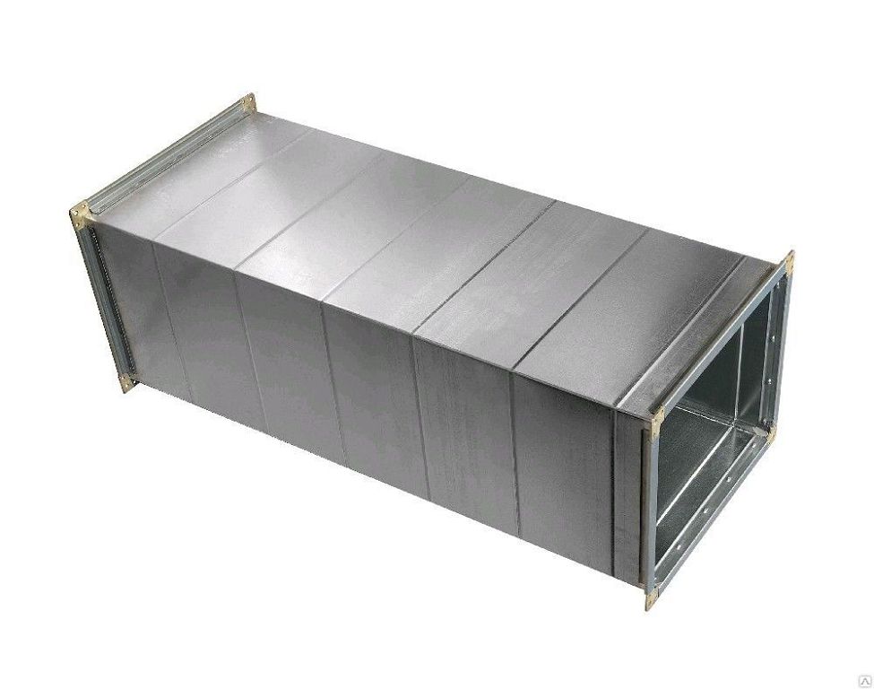
- Metal galvanized or black steel, stainless steel.
- Flexible aluminum or plastic film.
- Hard plastic.
- Fabric
The shape of the air ducts are made of round section, rectangular and oval. Round and rectangular pipes are most commonly used.
Most of the described ducts are manufactured in the factory, for example, flexible plastic or fabric, and it is difficult to manufacture them on site or in a small workshop. Most of the products that require calculation, made of galvanized steel or stainless steel.
Both rectangular and round air ducts are made of galvanized steel, and production does not require particularly expensive equipment. In most cases, a bending machine and a device for the manufacture of round pipes are sufficient. Apart from small hand tools.
Calculation of the duct cross-section
The main task that arises in the calculation of air ducts is the choice of the cross-section and shape of the product. This process takes place in the design of the system both in specialized companies and in independent production. It is necessary to calculate the diameter of the duct or the sides of the rectangle, to choose the optimal value of the cross-sectional area.
Calculation of the cross section is carried out in two ways:
- permissible speeds;
- constant pressure loss.
The method of permissible speeds is easier for non-specialists, so we will consider it in general terms.
Calculation of duct cross-section by the method of permissible speeds
The calculation of the ventilation duct section by the method of permissible speeds is based on the normalized maximum speed. The speed is selected for each type of room and duct section depending on the recommended values. For each type of building, there are maximum allowable speeds in the main ducts and branches, above which the use of the system is difficult due to noise and severe pressure losses.
Fig. 1 (Network diagram for calculation)
In any case, before starting the calculation it is necessary to make a plan of the system. First you need to calculate the required amount of air that must be supplied and removed from the room. Further work will be based on this calculation.
The process of calculating the cross section by the method of allowable speeds itself consists of the following steps:
- A scheme of air ducts is created, on which sections and the estimated amount of air that will be transported by them are marked. It is better to specify all grilles, diffusers, section changes, turns and valves on it.
- According to the selected maximum speed and the amount of air, the section of the duct is calculated, its diameter or the size of the sides of the rectangle.
- After all the parameters of the system are known, it is possible to pick up a fan of the required capacity and head. Fan selection is based on the calculation of the pressure drop in the network. This is much more difficult than just pick up the section of the duct at each site. This question we will consider in general terms. Since sometimes they just pick up the fan with a small margin.
To calculate the need to know the parameters of the maximum air velocity. They are taken from reference books and regulatory literature. The table shows the values for some buildings and areas of the system.
Standard speed
Values are approximate, but allow you to create a system with a minimum level of noise.
Figure 2 (nomogram round tin duct)

How to use these values? They must be substituted into the formula or use nomograms (schemes) for different forms and types of ducts.
Nomograms are usually given in the regulatory literature or in the instructions and description of the ducts of a particular manufacturer. For example, such schemes are completed with all flexible air ducts. For pipes made of tin, data can be found in the documents and on the manufacturer's website.
In principle, you can not use the nomogram, and find the desired cross-sectional area, based on the air velocity. A square to pick up the diameter or width and length of a rectangular section.
Example
Consider an example. The figure shows the nomogram for a circular duct of tin. The nomogram is also useful due to the fact that it is possible to clarify the pressure loss in the duct section at a given speed. These data will be required later for the selection of the fan.
So, which duct to pick up in the network area (branch) from the grille to the line through which 100 m³ / h will be pumped? On the nomogram we find the intersection of a given amount of air with a maximum speed line for a branch of 4 m / s. Also not far from this point we find the nearest (larger) diameter. This is a pipe with a diameter of 100 mm.
In the same way we find the cross section for each section. Everything is selected. Now it remains to carry out the selection of the fan and the calculation of air ducts and fittings (if it is necessary for production).
Fan selection
An integral part of the permissible velocity method is the calculation of pressure losses in the duct network for the selection of a fan of the required capacity and head.
Pressure loss in straight sections
In principle, the required performance of the fan can be found by adding the required amount of air for all premises of the building and selecting the appropriate model in the manufacturer's catalog. But the problem is that the maximum amount of air specified in the documentation for the fan, he is able to supply only without a duct network. And when you connect the pipe, its performance will fall depending on the pressure loss in the network.
For this, each fan in the documentation is given a performance chart depending on the pressure drop in the network. But how to calculate this fall? For this you need to determine:
- pressure drop on flat ducts;
- losses on grids, turns, tees and other shaped elements and obstacles in the network (local resistances).
Pressure losses in duct sections are calculated using the same nomogram shown. From the point of intersection of the air velocity line in the selected duct and its diameter, we find the pressure loss in pascals per meter. Next, we calculate the total pressure loss in the area of a certain diameter by multiplying the specific loss by the length.
For our example with a duct of 100 mm and a speed of about 4 m / s, the pressure loss will be about 2 Pa / m.
Losses of pressure on local resistances
The calculation of pressure losses in turns, bends, tees, section changes and transitions is much more complicated than in straight sections. For such on the same above scheme, all the elements that can impede movement are indicated.
Figure 3 (Some KM. SS.)

Next, it is necessary for each such local resistance in the normative literature to find the coefficient of local resistance (km. S), which is denoted by the letter ζ (zeta). The pressure loss on each such element is given by the formula:
Pm c. = ζ × Pd
where Pd = V2 × ρ / 2 is the dynamic pressure (V is the velocity, ρ is the air density).
For example, if in the area already considered by us with a diameter of 100 mm with a speed of air movement of 4 m / s there will be a round elbow (rotate 90 degrees) km. which 0.21 (according to the table), the pressure loss on it will be
- Pm s. = 0.21 · 42 · (1.2 / 2) = 2.0 Pa.
The average density of air at a temperature of 20 degrees is 1.2 kg / m3.
Figure 4 (Example table)
According to the found parameters the fan is selected.
Material calculation for air ducts and fittings
The calculation of the area of air ducts and fittings is necessary during their production. It is done in order to determine the amount of material (tin) for the manufacture of a pipe section or any shaped element.
For calculation it is necessary to use only formulas from geometry. For example, for a circular duct we find the diameter of a circle, by multiplying which by the length of the section we obtain the area of the outer surface of the pipe.
For the manufacture of 1 meter pipe with a diameter of 100 mm you will need: π · D · 1 = 3.14 · 0.1 · 1 = 0.314 m² of tin. It is also necessary to consider from 10-15 mm of stock per connection. Also calculated and rectangular duct.
The calculation of the shaped parts of air ducts is complicated by the fact that there are no definite formulas for it, as for a round or rectangular section. For each element it is necessary to cut and calculate the required amount of materials. This is done in manufacturing or in tin workshops.
The main factor affecting the performance of the ventilation system is its proper design. For the system to function properly, it is necessary to make clear calculations of the duct area. Correctly performed calculation of air ducts is responsible for:
- the level of noise generated;
- the amount of electricity consumed;
- system tightness;
- unimpeded passage of air at the required speed and in the right volumes.
You can simplify the calculation process with the help of specialized programs (calculators) or by contacting one of the relevant companies. For an independent search for the necessary parameters, there are calculation formulas, which, however, will be incomprehensible to a person without proper education. The most popular formulas are calculations for any engineering work related to the design of ventilation systems.
To perform calculations using formulas, you must enter the required values instead of letters and perform a calculation. The accuracy of the final result depends solely on the clarity of the initial parameters obtained in the measurement process.
Finding the right values
Initially, to calculate the area, you need to get the information:
- the least air flow requirements;
- about the highest air flow rate.
- Depends on correct measurements and calculations:
- the level of vibration and airborne noise, the limit of which depends on the accuracy of calculations;
- air flow rate, which can cause both increased energy consumption and increased pressure;
- level of tightness - only with proper calculations the ventilation system will be tight.
During the design of the ventilation system it is extremely important to pay attention to all sorts of aspects in such a way that with this approach the system will be practical and no less durable. In addition, only properly designed ventilation without any problems to cope with their original tasks. In particular, it is important to pay attention to the calculations when installing the ventilation system in large industrial and public premises.
The air flow velocity depends on the value of the cross-sectional area - the larger it is, the faster the air moves. Also, the value of this value will greatly reduce the level of energy consumption and aerodynamic noise of the system. Due to the large cross-sectional dimensions, the total cost of the ventilation system increases. In addition, such ventilation can not be installed in rooms with suspended ceiling. The problem can be solved by using rectangular ducts, but at the same time sacrificing substantial operational advantages of round products.
Ultimately, only user preferences determine which system is best to choose. If you need the greatest energy savings and the complete absence of aerodynamic noise is ideal square ventilation system. However, such ventilation takes up a lot of space. If the priority is only ease of installation or indoors it is impossible to install a bulky rectangular system, you should pay attention to products with a circular cross section.
With due attention to the design process, you can easily achieve the perfect ventilation system.
Formula Calculations
When performing calculations, one should be guided by the formula intended for this purpose:
Sc = L * 2.778 / V,
Here Sc is the section area; L - air flow (m2 / h); V is the air velocity at a specific location of the structure (m / s); 2.778 - fixed coefficient.
After all the required calculations, the result will be a number in square centimeters.
To find out the actual area of ventilation, use the appropriate formulas:
- round products - S = Pi * D squared / 400;
- rectangular products - S = A * B / 100.
Legend, here S is the area; D is the diameter; A and B - the size of the duct.
Only after all the calculations are completed and the result is rechecked, you can proceed to the actual installation work. By this time, the entire ventilation system project should be completed.
Pressure loss
Being in the air duct of the ventilation system, the air experiences some resistance. To overcome it, the system must have an appropriate level of pressure. It is generally accepted that air pressure is measured in its own units - Pa.
All necessary calculations are carried out using a specialized formula:
P = R * L + Ei * V2 * Y / 2,
Here P is the pressure; R - partial changes in pressure level; L - the overall dimensions of the entire duct (length); Ei is the coefficient of all possible losses (summed up); V is the air velocity in the network; Y is the density of air flow.
Acquainted with all sorts of symbols that are found in the formulas, possibly with the help of special literature (reference books). At the same time, the value of Ei is unique in each individual case due to the dependence on a certain type of ventilation.
Other all kinds of help can be obtained at specialized forums on the Internet. However, the opinion of each specialist is unique in its own way.
Heater power
To determine the most suitable power of the heating device, it is necessary to consider:
- required temperature values;
- indicator of the lowest possible temperature outside the room.
Experts accepted that the minimum level of temperature inside the ventilation systems does not exceed 18 degrees Celsius. Internal temperature conditions depend solely on the external climate. For ordinary apartments, a heater with a power of 1–5 kW is most suitable. Public (including office) premises require a more productive device, whose power is 5–50 kW.
To perform the most accurate calculations of the required heater power, you can use the following formula:
P = T * L * Cv / 1000,
Here P is the heater power (kW); T is the difference between the main temperatures (indoors and outside); L - efficiency of the ventilation system; Cv is the heat capacity (0.336 W * h / square meters / degree Celsius).
Having made the necessary calculations, you can easily choose a suitable air heater that fully meets the user's preferences. In addition, the accuracy of the results will affect the subsequent operation of the ventilation system.
Shaped products
 To calculate the required parameters of both shaped products and the ventilation itself, there is no need to independently use formulas. To simplify the entire design process, engineers created specialized programs (calculators) that are able to calculate themselves. The only thing that is required from the user is to enter the requested values.
Independently calculate the value for fasteners fittings can only engineer. However, even professionals are not able to do without special tables, values and formulas with the necessary coefficients. A person without sufficient knowledge in the relevant areas is not capable of independently designing.
When calculating the diameter of the duct is necessary to use a table of equivalent diameters. This table takes into account air ducts with a large cross-section, where the reduction of pressure on friction is equivalent to the reduced pressure of rectangular structures. Equivalent diameters are necessary only if it is necessary to perform a calculation of rectangular facades using tables for structures with a large section (round).
In both cases, a professional approach to computing is needed. If any parameters are not true, the ventilation system will not work.
Equivalent (equivalent) value can be found in one of three ways:
- by air flow;
- by air flow rate;
- across the duct cross-section.
Each of these values is fully associated with any parameter of the ventilation system. To determine each parameter you will need to use an individual calculation table. As a final result, the value of pressure loss on friction is obtained. If all measurements were correct, regardless of the method of calculation, the result will be completely identical. Errors in calculations may occur due to violation of measurement requirements.
Additionally
More detailed information on design (tables, formulas, reference books, etc.) can be easily found on the Internet in various subject forums. The end result (the strength of both the structure itself and its anchorages) completely depends on the correctly chosen measuring instruments. It is easiest to make the required measurements using special calculators and other engineering programs. In this case, you will not need to perform calculations yourself - you just need to enter the requested numbers.
In the case of online calculators, the result will be more accurate than with manual calculations. This is due to the fact that the program itself, in automatic mode, seeks to round the result to a more accurate and understandable value.
Modern blessings of civilization make it possible to equip a house at will, equipping a dwelling with all the items necessary for comfortable living, including supply chains. Is it possible to imagine a modern house without a ventilation system and air conditioning? Today it seems unreal, but after all, before people did not know about such benefits.
Arrangement of ventilation passages is not just words. Such work will have to be approached with no less responsibility than the design of the house. Arrangement of the building as a whole - from laying the foundation and before putting it into operation is a responsible and important process.
From that, the ventilation system is how correctly designed, its further functioning depends. Every detail is important here. After all, assuming even a small error, the system can fail and, for example, instead of cold air, drive hot inside the room. The ventilation system consists of a set of elements that are interconnected by special parts and fittings.
Features of the design of ventilation in the house
The main factor affecting the performance of the ventilation system - the correct design. The calculation of the area of air ducts and fittings is necessary for the coordinated work of the entire system. Computing is a laborious and time-consuming business. Although today this process is easy to carry out with the use of special formulas or whole computer programs.
Features of calculation by the formula
The calculation of the area of air ducts and fittings according to the formula is as follows:
Sc = L * 2.778 / V, where:
- Sc - section area;
- L is the flow rate of the circulating flow;
- V is the flow velocity at a specific place (m / s);
- 2,778 - fixed value (coefficient).
After calculating the area of ducts and fittings, you can get the number, measured in cm 2.
Regular ventilation area
To calculate the indicator use:
- S = p * D 2/400 - for round products;
- S = A * B / 100 - for rectangular products.
Here S is the area, D is the diameter of the air duct / pipe, A, B is the size of the ventilation ducts.

Pressure loss during air circulation
The design of the ventilation system has its own subtleties. Conducting such work, it is important not to forget about the possible loss of pressure in the network during continuous air circulation. For this purpose, a special formula has been prepared, showing the degree of pressure level in the network required for normal functioning:
P = R * L + Ei * V2 * Y / 2, where:
- P is the pressure level in the system;
- R is the rate of change in pressure in the network;
- L is the length of the duct;
- Ei is the summed loss coefficient;
- V is the air velocity inside the network;
- Y - the density of the air through the pipe.
Shaped products
To determine the necessary parameters and components of ventilation, it is necessary to have mathematical skills to be able to use formulas to determine the area of ducts and other indicators required during the design of the ventilation system. To simplify the design process, engineers have been working on improving special programs for several years — calculators that are able to calculate automatically. A person only needs to manually enter the requested values to calculate the duct area and the program will do the rest.

Independently calculate the values for fittings fittings under the force only a specialist - an engineer. Although even the professionals in their field rarely do without special tables with coefficients, symbols and permissible norms for the circulation of air flows. Without a formula for calculating the area of ducts and fittings in this work is not enough.
An ordinary person without knowledge in certain areas of engineering cannot do the complicated steps of calculations. Therefore, when designing not only ventilation, but also any other communication system, take for yourself doing only the work you can do, and entrust the rest to professionals if you need a house with well-functioning communication systems and an optimal indoor climate, regardless of the weather outside.
The performance of the ventilation system depends on the correctness of its design. The most important role in this is played by the correct calculation of the duct area. It depends on him:
- Unimpeded movement of the air flow in the right volumes, its speed;
- Tightness of the system;
- Noise level;
- Electricity consumption.
In order to find out all the necessary values, you can contact the relevant company or use special programs (they can be easily found on the Internet). However, if necessary, it is possible to find all the necessary parameters on your own. For this there are formulas.
Using them is quite simple. You also need to enter the parameters instead of the corresponding letters and find the result. Formulas will help you find the exact values, taking into account all individual factors. Usually they are used in engineering work on the design of the ventilation system.
How to find the correct values
In order to calculate the cross-sectional area, we need the information:
- About the minimum required air flow;
- About the maximum possible air flow rate.
Why do we need the correct calculation of the area:
- If the flow rate is higher than the set limit, this will cause a pressure drop. These factors, in turn, will increase electricity consumption;
- Aerodynamic noise and vibration, if everything is done correctly, will be within the normal range;
- Providing the necessary level of tightness.

It will also improve the efficiency of the system, help make it durable and practical. Finding the optimal network parameters is a crucially important point in the design. Only in this case, the ventilation system will last a long time, perfectly coping with all its functions. This is especially true for large premises of public and industrial importance.
The larger the section will be, the lower the air flow rate will be. It will also reduce aerodynamic noise and power consumption. But there are also disadvantages: the cost of such air ducts will be higher, and the structures cannot always be installed in the space above the suspended ceiling. However, this is possible with rectangular products whose height is less. At the same time, round shaped products are easier to install and have important operational advantages.
What exactly to choose depends on your requirements, the priority of energy saving, the very characteristics of the room. If you want to save electricity, make the noise minimal and you have the opportunity to install a large network, choose a rectangular system. If the priority is simplicity of installation or it is difficult to install structures of rectangular type indoors, you can choose products of circular section.
The area is calculated using the following formula:
Sc = L * 2, 778 / V
Sc here - sectional area;
L is the air flow rate in cubic meters / hour;
V - air velocity in the duct in meters per second;
2,778 - the required ratio.

After the calculation of the area is completed, you will get the result in square centimeters.
The actual area of the ducts will help determine the following formulas:
For round: S = Pi * D squared / 400
For rectangular: S = A * B / 100
S here is the actual cross-sectional area;
D is the diameter of the structure;
A and B - height and width of structures.
How to determine pressure loss
The calculation of the network resistance allows you to take into account the pressure loss. The air flow, while moving, experiences a certain resistance. Appropriate pressure is important to overcome it. This pressure is measured in Pa.
To find out the desired parameter, you need the following formula:
P = R * L + Ei * V2 * Y / 2
R here - specific reduction of pressure on friction in the network;
L is the length of the ducts;
Ei - total local network loss rate;
V is the air velocity in the considered network area;
Y is the air density.
R can be found in the corresponding directory. Ei depends on local resistance.
How to find out the optimal power of the air heater
In order to find out the optimal power of the air heater, indicators of the required air temperature and the minimum temperature outside the room are required.

The minimum temperature in the ventilation system is 18 degrees. The temperature outside the room depends on the climatic conditions. For apartments, the optimal heater power is usually from 1 to 5 kW, for office space - 5-50 kW.
The exact calculation of heater power in the network will allow you to perform the following formula:
P = T * L * Cv / 1000
P here - heater power in kW;
T is the temperature difference between the air inside and outside the room. This value can be found in the SNiP;
L is the productivity of the ventilation system;
Cv is the heat capacity equal to 0.336 W * h / square meters / degree Celsius.
Additional Information
In order to find out the necessary parameters of fittings and the structure itself, it is not necessary to independently calculate the parts of the ventilation network. To find all the values there are special programs. You just need to enter the required numbers and you will get the result in a split second.
The values of fasteners, fittings, ducts are usually calculated by engineers involved in the design of ventilation systems. But also they use tables in which there are all required coefficients, formulas, values.
There is also a special table of equivalent duct diameters. This is a table of diameters of round-shaped blowers in which the decrease in pressure on friction is equal to the decrease in pressure in rectangular structures. Equivalent diameter of the design of the blower is required when it is necessary to calculate rectangular blowers, and in this case the table is used for products of round shape.

There are three ways to find out the equivalent value:
- Focusing on speed;
- By cross section;
- By consumption.
All these values are related to the width and other values of the ducts. For each of the parameters, a different method of using tables is applied. The final result is the value of pressure loss on friction. Regardless of what method you applied, the result is the same.
On the Internet, you can easily find tables, programs, reference books necessary for calculating the area and other parameters of the structures themselves, fixtures. The simplest is to use special programs. In this case, you are only required to enter the desired values. In this case, the results you get pretty accurate.

 Reception of indications of counters of hot and cold water supply
 Chemistry of combustion processes. Explosion energy
 What will happen if you do not transmit meter readings